Timer And Contactor R Relay Diagram - How To Wire Ah3 3 Timer - Sdt 20 thermistor klixon start relay motor sdt 100 thermistor sdt 1000 thermistor star.. Thus relay will be on. Another device similar to the relay is the timer, pictured below:. However, configuring a certain number of time relays and intermediate relays can do it. V = voltage r = reset s1 = initiate switch td = time delay. Using an ohmmeter, test between 2 testing compressor contactor.
Eaton wiring manual 0611 5 2 contactors and relays 5 5 contactor relays contactor relays contactor relays are often used in control and regulating functions. The contactor relays diler and dila fulfil this requirement. It reveals the components of the circuit as simplified shapes and also the power and signal connections in between the tools. Adjusting the delay time is often as simple as turning a knob. Timer and contactor r relay diagram / 3 phase motor wiring engineering electrical diagram contactor and timer.
Contactor Wiring Diagram With Timer New 240 Volt Hvac Wiring Wiring Diagram Write Electrical Wiring Diagram House Wiring Electrical Diagram from i.pinimg.com Mar 26, 2021 · timer and contactor r relay diagram : Timer and contactor r relay diagram / 3 phase motor wiring engineering electrical diagram contactor and timer. Literally, a circuit is the path that permits electrical energy to. Contactor relays dil two contactor relay series are available as a modular system: Ladder diagram or electrical schematic or elementary diagram can be divided into two. Using an adapter plate, you can also mount it for standalone use. Dim dip unit & glow plug timer. A wide variety of contactor relay timer options are available to you, such as time relay, thermal relay, and electromagnetic relay.
Timer and contactor wiring diagram pdf.
Contactor wiring to timer talk about wiring diagram. Another device similar to the relay is the timer, pictured below:. Using an adapter plate, you can also mount it for standalone use. However, configuring a certain number of time relays and intermediate relays can do it. These are basic element for rlc. Timer and contactor wiring diagram pdf. Octopart is the preferred search engine for electronic parts. Time relay is widely used in remote control, telecommunication, automatic control and other electronic equipment, and is one of the most important control components. To understand and create rlc, we must have to know about the basic element. Dim dip unit & glow plug timer. It reveals the components of the circuit as simplified shapes and also the power and signal connections in between the tools. Contactor relays dil two contactor relay series are available as a modular system: All type r relays with a manual operator must be used on circuits of the same polarity.
Either of the two start buttons will close the contactor either of the stop buttons will open the contactor. Class 9999 type xtd and xte. Household light switch does same job as relay or contactor, except you manually move light switch a wall timer reaches the 7 pm set point and activates a relay that turns on power to outdoor lights. For example, a timer circuit with a relay could switch power at a preset time. V = voltage r = reset s1 = initiate switch td = time delay.
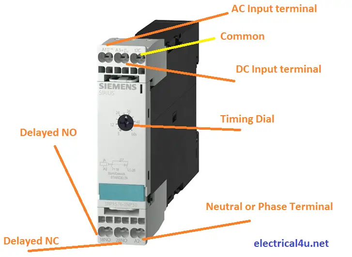
What Is Star Delta Timer Circuit Diagram Working Siemens Electrical4u from www.electrical4u.net V = voltage r = reset s1 = initiate switch td = time delay. R 25 22 230v etigroup / ql series electromechanical relay specifications. Ladder diagram or electrical schematic or elementary diagram can be divided into two. I am looking to build a circuit that would control an output relay. At the same time, it is necessary to ensure that the contact gaps are at least 0.5 mm over the lifespan, even when defective (e.g. When a contact is welded). Now in the diagram below i have added a motor starter. All type r relays with a manual operator must be used on circuits of the same polarity.
Timer and contactor r relay diagram :
240 volts ac and 480 volts ac are commonly used for these large pieces of. Sdt 20 thermistor klixon start relay motor sdt 100 thermistor sdt 1000 thermistor star. Time relay is widely used in remote control, telecommunication, automatic control and other electronic equipment, and is one of the most important control components. Relay logic is a method of operating industrial electrical circuits with the help of relay and contacts. The output contact switches the coil of the line contactor. Hager contactor wiring diagram single phase 1 with overload and. Not applicable with electronic timer accessories (crz_7). Abb's contactor relays offering features products of technological advancement as well as products with specific purposes. These are basic element for rlc. Types, working and difference between them. A very first check out a circuit representation may be confusing, however if you can read a train map, you can review schematics. Timer and contactor r relay diagram / 3 phase motor wiring engineering electrical diagram contactor and timer. Another device similar to the relay is the timer, pictured below:.
Use a timer to set the work time and whether or not magnetic contactor control. Timer and contactor r relay diagram : Not applicable with electronic timer accessories (crz_7). Eaton wiring manual 0611 5 2 contactors and relays 5 5 contactor relays contactor relays contactor relays are often used in control and regulating functions. At the same time, it is necessary to ensure that the contact gaps are at least 0.5 mm over the lifespan, even when defective (e.g.
Relay Wikipedia from upload.wikimedia.org Contactor switching time is higher than relay. Timer and contactor r relay diagram : When a contact is welded). First we understand what is no and nc point. Obtaining from factor a to point b. Ladder diagram or electrical schematic or elementary diagram can be divided into two. To understand and create rlc, we must have to know about the basic element. Hager contactor wiring diagram single phase 1 with overload and.
Timer and contactor r relay diagram :
Relay logic basically consists of relays wired up in a particular fashion to perform the desired switching operations. Obtaining from factor a to point b. Thus relay will be on. These are basic element for rlc. Overload relays may be set for 2 different operational modes—manual reset only or. Ql series electromechanical relay specifications. Now in the diagram below i have added a motor starter. Either of the two start buttons will close the contactor either of the stop buttons will open the contactor. Smallest size (10.2 × 18.2 × 14.8 mm) at 10a. I am looking to build a circuit that would control an output relay. However, configuring a certain number of time relays and intermediate relays can do it. Timer and contactor wiring diagram pdf. Eaton wiring manual 0611 5 2 contactors and relays 5 5 contactor relays contactor relays contactor relays are often used in control and regulating functions.


0 Comments